Description
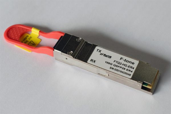
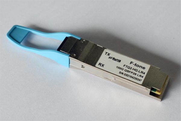
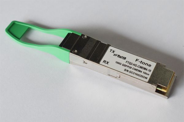
The F-tone Networks 100GE CWDM4 2km QSFP28 optical transceiver (FTQ2-HG-CWDM4-02xx) is designed for use in 100-Gigabit Ethernet links up to 2km on Single Mode Fiber (SMF). It is compliant with the QSFP28 MSA, CWDM4 MSA and relevant portions of IEEE 802.3bm. Digital diagnostics functions are available via an I2C interface, as specified by the QSFP28 MSA. It converts 4 input channels of 25.78125Gb/s electrical data to 4 channels of CWDM optical signals and then multiplexes them into a single channel for 103.125Gb/s optical transmission. Reversely on the receiver side, the module de-multiplexes a 103.125Gb/s optical input into 4 channels of CWDM optical signals and then converts them to 4 output channels of electrical data. The central wavelengths of the 4 CWDM channels are 1271nm, 1291nm, 1311nm and 1331nm as members of the CWDM wavelength grid defined in CWDM4 MSA.
Features
● Hot-pluggable QSFP28 form factor
● 4 channels full-duplex transceiver module
● Supports 103.125Gb/s aggregate bit rate
● 4 channels DFB-based CWDM uncooled transmitter
● 4 channels PIN ROSA
● Internal CDR circuits on both receiver and transmitter channels
● 3.5W maximum power dissipation
● Maximum link length of 2km on SMF with KR4 FEC
● Duplex LC receptacle
● Single 3.3V power supply
● RoHS-6 compliant (lead free)
● Case operating temperature
Commercial: 0 ~ +70℃
Industrial: -40 ~ +85℃
Applications
● 100GE CWDM4 applications with FEC
Absolute Maximum Ratings
| Parameter | Symbol | Min | Max | Unit |
| Supply Voltage | Vcc | -0.3 | 3.6 | V |
| Input Voltage | Vin | -0.3 | Vcc+0.3 | V |
| Storage Temperature | Ts | -20 | 85 | ºC |
| Case Operating Temperature | Tc | 0 | 70 | ºC |
| Humidity (non-condensing) | Rh | 5 | 85 | % |
| Damage Threshold (each lane) | THd | 5.5 | dBm |
Recommended Operating Conditions
| Parameter | Symbol | Min | Typical | Max | Unit |
| Supply Voltage | Vcc | 3.13 | 3.3 | 3.47 | V |
| Operating Case Temperature | Tc | 0 | 70 | ºC | |
| Data Rate Per Lane | fd | 25.78125 | Gb/s | ||
| Humidity | Rh | 5 | 85 | % | |
| Power Dissipation | Pm | 3.5 | W | ||
| Link Distance with G.652 | D | 0.002 | 2 | km |
Electrical Specifications
| Parameter | Symbol | Min | Typical | Max | Unit |
| Supply Current | Icc | 1.12 | A | ||
| Transceiver Power-on Initialization Time1 | 2000 | ms | |||
| Transmitter (each Lane) | |||||
| Single-ended Input Voltage Tolerance | -0.3 | 4.0 | V | ||
| AC Common Mode Input Voltage Tolerance | 15 | mV | |||
| Differential Input Voltage | 50 | mVp-p | |||
| Differential Input Voltage Swing | Vin | 190 | 1000 | mVp-p | |
| Differential Input Impedance | Zin | 90 | 100 | 110 | Ohm |
| Receiver (each lane) | |||||
| Single-ended Output Voltage | -0.3 | 4.0 | V | ||
| AC Common Mode Output | 7.5 | mV | |||
| Differential Output Voltage Swing | Vout | 300 | 900 | mVp-p | |
| Differential Output Impedance | Zout | 90 | 100 | 110 | Ohm |
Note:1. Power-on Initialization Time is the time from when the power supply voltages reach and remain above the minimum recommended operating supply voltages to the time when the module is fully functional.
Optical Characteristics
| Parameter | Symbol | Min | Typical | Max | Unit |
| Lane Wavelength | L0 | 1264.5 | 1271 | 1277.5 | nm |
| L1 | 1284.5 | 1291 | 1297.5 | nm | |
| L2 | 1304.5 | 1311 | 1317.5 | nm | |
| L3 | 1324.5 | 1331 | 1337.5 | nm | |
| Transmitter | |||||
| Side Mode Suppression Ratio | SMSR | 30 | dB | ||
| Total Average Launch Power | PT | 8.5 | dBm | ||
| Average Launch Power (each Lane) | PAVG | -6.5 | 2.5 | dBm | |
| Optical Modulation Amplitude1 (each lane) | POMA | -4.0 | 2.5 | dBm | |
| Launch Power in OMA minus TDP | -5 | dB | |||
| Transmitter and Dispersion Penalty (TDP) (each lane) | TDP | 3.0 | dB | ||
| Extinction Ratio | ER | 3 | dB | ||
| Relative Intensity Noise | RIN | -130 | dB/Hz | ||
| Optical Return Loss Tolerance | TOL | 20 | dB | ||
| Transmitter Reflectance | RT | -12 | dB | ||
| Average Launch Power of OFF transmitter (each lane) | POFF | -30 | dBm | ||
| Eye Mask Coordinates2: X1, X2, X3, Y1, Y2, Y3 | {0.31, 0.4, 0.45, 0.34, 0.38, 0.4} | ||||
| Receiver | |||||
| Damage Threshold3 (each lane) | THd | 3.5 | dBm | ||
| Average Receive Power (each lane) | -11.5 | 2.5 | dBm | ||
| Receive Power (OMA) (each lane) | 2.5 | dBm | |||
| Receiver Sensitivity (OMA)4 (each lane) | SEN | -10 | dBm | ||
| Stressed Receiver Sensitivity (OMA)5(each Lane) | -7.3 | dBm | |||
| LOS Assert | -16 | dBm | |||
| LOS De-Assert – OMA | -14 | -7.5 | dBm | ||
| LOS Hysteresis | 0.5 | 2 | dB | ||
| Receiver Electrical 3 dB upper Cutoff Frequency (each Lane) | Fc | 31 | GHz | ||
| Conditions of Stress Receiver Sensitivity Test6 | |||||
| Vertical Eye Closure Penalty6 | VECP | 1.9 | dB | ||
| Stressed Eye J2 Jitter | J2 | 0.33 | UI | ||
| Stressed Eye J4 Jitter | J4 | 0.48 | UI | ||
Note:
- Even if the TDP <1dB, the OMA min must exceed the minimum value specified here.
- Hit ratio of 5e-5, per IEEE; See Figure 2 below.
- The receiver shall be able to tolerate, without damage, continuous exposure to a modulated optical input signal having this power level on one lane. The receiver does not have to operate correctly at this input power.
- Measured with conformance test signal at receiver input for BER = 5e-5 BER.
- Measured with CWDM4 MSA conformance test signal at TP3 for 5e-5
- Vertical eye closure penalty and stressed eye jitter are test conditions for measuring stressed receiver sensitivity. They are not characteristics of the receiver.
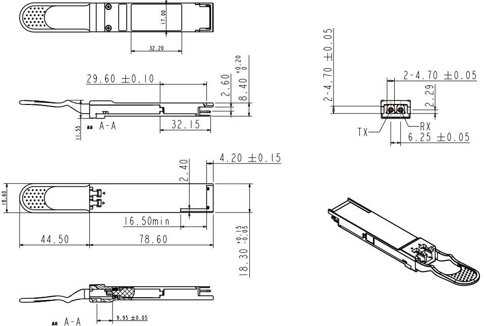
Mechanical Dimensions
Ordering Information
| Product Description | Part Number |
| QSFP28 CWDM4, 103.125Gb/s, 1310nm, 2km, SMF, LC, 0 ~ +70℃ | FTQ2-HG-CWDM4-02 |
| QSFP28 CWDM4, 103.125Gb/s, 1310nm, 2km, SMF, LC, -40 ~ +85℃ | FTQ2-HG-CWDM4-02I |
北亿纤通 | F-tone Networks
企业邮箱: sales@f-tone.com
企业手机:19081343401
企业电话:028-85255257
企业传真:028-85977702
注:本产品有全国产化型号可选
Important Notice
Performance figures, data and any illustrative material provided in this data sheet are typical and must be specifically confirmed in writing by F-tone Networks before they become applicable to any particular order or contract. In accordance with the F-tone Networks policy of continuous improvement specifications may change without notice.
The publication of information in this data sheet does not imply freedom from patent or other protective rights of F-tone Networks or others. Further details are available from any F-tone Networks sales representative.
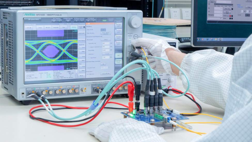
光学性能测试
测试光纤收发模块的眼图情况、接收灵敏度、消光比、波长、发光、光接收、电流和电压,以确保信号质量、传输的稳定性和可靠性。
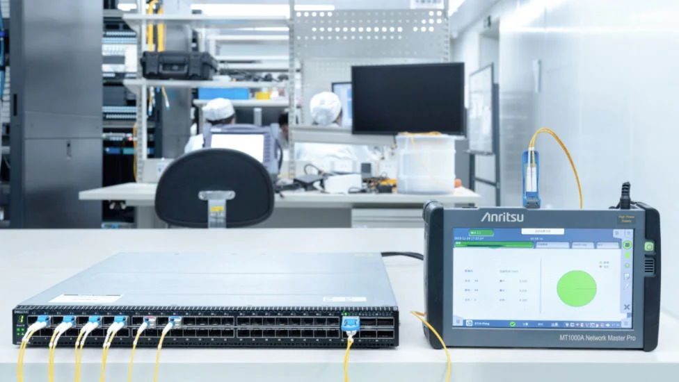
Traffic Testing
测试误码率和丢包率,使其符合相应标准,确保收发器的性能。
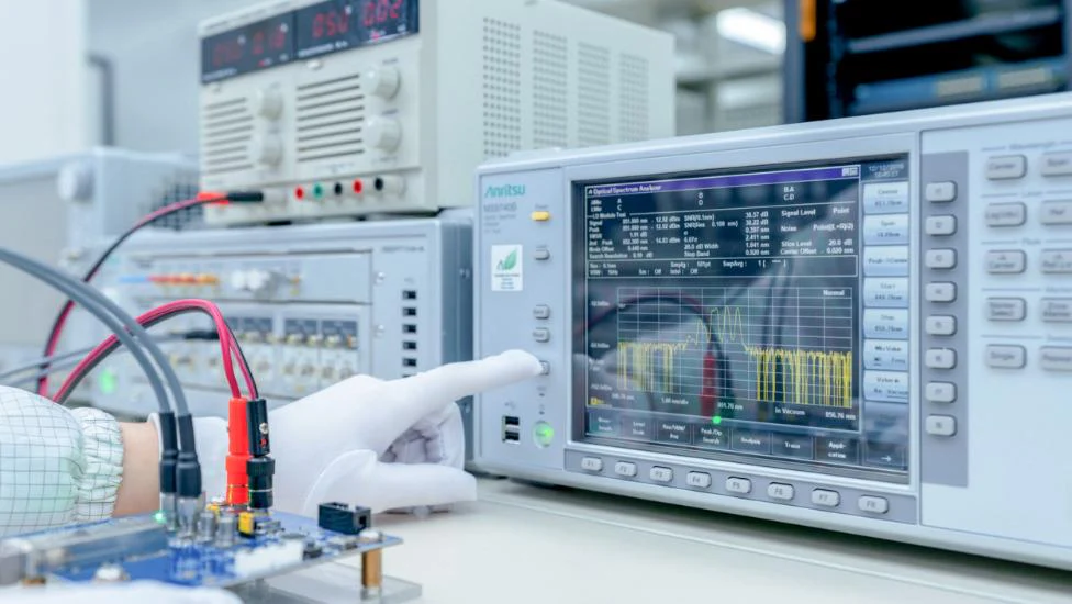
光学性能测试
测试光纤收发模块的眼图情况、接收灵敏度、消光比、波长、发光、光接收、电流和电压,以确保信号质量、传输的稳定性和可靠性。
端面测试
检查光纤收发模块的端面并保持清洁,以实现更稳定的数据传输、更好的性能和耐用性。

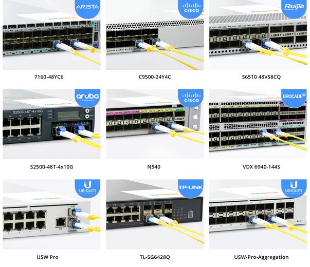
兼容品牌:
华为 | 华三 | 中兴 | 锐捷 | Cisco | Juniper | Arista | Brocade |HPE ProCurve | HPE Aruba | HPE BladeSystem | HPE H3C | H3C | Dell | Extreme | HW | Generic | F-tone | Intel | Netgear | IBM | NVIDIA/Mellanox (Ethernet) | Ciena | Fortinet | Avago | Avaya | Alcatel-Lucent | D-Link | F5 | Ubiquiti | Mikrotik |Broadcom…..