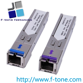
F-tone SFP GEPON ONU Stick Transceiver 1000BASE-PX20
FONU-SFP-20X
Features
-
IEEE 802.3ah™-2004 1000BASE-PX20 GEPON ONU side application
-
EPON standard OAM control
-
Single SMF 1310nm/1490nm bi-directional transmission with symmetric 1.25Gbps upstream / downstream
-
Up to 32 subscribers within 20km radius
-
“Plug-and-play” via auto-discovery and configuration
-
Optical link measurement and diagnosis
-
Secure access via Access Control List (ACL)
-
Triple Churning Key decryption
-
IEEE 802.3ah Forward Error Correction (FEC)
-
Highly flexible 802.1Q VLAN support
-
802.1p/q support
-
Advanced QoS functions enable billing by Service Level Agreement (SLA)
-
IGMP Snooping
-
Operating case temperature: 0~80°C
-
Low EMI and excellent ESD protection
-
Class��laser safety standard IEC-60825 compliant
-
FONU-SFP-20X Complies with CTC standard
-
FONU-SFP-20B Complies with DPOE standard
-
Complies with RoHS-6
Applications
-
Ethernet Passive Optical Networks– ONT/ONU side
Standard
-
Compliant with SFF MSA - 2000
-
Compliant with SFF-8472 Rev.11.0
-
Compliant with IEEE Std 802.3ah™ -2004
-
Compliant with FCC 47 CFR Part 15, Class B
-
Compliant with FDA 21 CFR 1040.10 and 1040.11, Class��
-
Complies with China Telecom EPON equipment technology requirement V3.0
Description
The FONU-SFP-20X is an IEEE 802.3ah- compliant Ethernet Passive (EPON) Optical Network Units (ONU) with Small Form-factor Pluggable (SFP) packaging.
The FONU-SFP-20X integrates a bi-directional optical transceiver function and an EPON MAC function. By being plugged into the customer premise equipment (CPE) with standard SFP port directly, the FONU-SFP-20X provides a symmetric 1.25Gbps upstream/downstream EPON uplink to the CPE without requiring separate power supply.
The FONU-SFP-20X supports all the functions needed to comply with the standard for EPON.
The FONU-SFP-20X supports a sophisticated ONU management system, including alarms, provisioning, DHCP and IGMP functions for a stand-alone IPTV solution at the ONU.
The FONU-SFP-20X can be managed from the OLT over the EPON using IEEE 802.3ah -2004 standard OAM messaging.
The FONU-SFP-20X fits seamlessly into existing communications equipment, providing service providers with a smooth upgrade to EPON. The FONU-SFP-20X solution vastly decreases the installation costs of deploying fiber access in MDUs and enables service providers to improve their revenue streams while decreasing OPEX.
Absolute Maximum Ratings
|
Parameter |
Symbol |
Minim |
Maxim |
Unit |
Note |
|
Storage Ambient Temperature |
TSTG |
-40 |
85 |
°C |
|
|
Operating Case Temperature |
Tc |
-10 |
85 |
°C |
|
|
Operating Humidity |
OH |
5 |
95 |
% |
|
|
Power Supply Voltage |
VCC |
0 |
4 |
V |
|
|
Receiver Damaged Threshold |
|
0 |
|
dBm |
|
Recommended Operating Conditions
Parameter
|
Symbol |
Minim |
Typical |
Maxim |
Unit |
Note |
|
Power Supply Voltage |
VCC |
3.13 |
3.3 |
3.47 |
V |
3.3V±5% |
|
Operating Current |
Icc |
|
|
750 |
mA |
|
|
Operating Case Temperature |
Tc |
0 |
|
80 |
°C |
|
|
Operating Humidity Range |
OH |
|
|
85 |
% |
|
|
Data Rate upstream |
|
|
1.25 |
|
Gbit/s |
|
|
Data Rate downstream |
|
|
1.25 |
|
Gbit/s |
|
|
Data Rate Drift |
|
-100 |
|
+100 |
PPM |
|
Transmitter Optical Characteristics
|
Parameter |
Symbol |
Minum |
Typical |
Maxim |
Unit |
Note |
|
Optical Center Wavelength |
λC |
1260 |
1310 |
1360 |
nm |
|
|
RMS Optical Spectrum Width |
∆λ |
|
|
3 |
nm |
5 |
|
Average Launch Optical Power |
Po |
0 |
|
4 |
dBm |
1 |
|
Power-OFF Transmitter Optical Power |
Poff |
|
|
-45 |
dBm |
|
Extinction Ratio |
ER |
9 |
|
|
dB |
2 |
|
Rise/Fall Time (20%-80%) |
TR/TF |
|
|
260 |
ps |
2,3 |
|
Optical Return Loss Tolerance |
|
|
|
15 |
dB |
|
|
Transmitter Reflectance |
|
|
|
-10 |
dB |
|
|
Transmitter and Dispersion Penalty |
TDP |
|
|
1.8 |
dB |
|
|
Optical Waveform Diagram |
Compliant With IEEE 802.3ah-2004 |
|
|
Data Input Differential Swing |
Vinp-p |
200 |
|
1600 |
mV |
4 |
|
Input Differential Impedance |
Zin |
90 |
100 |
110 |
Ω |
|
|
Transmitter disable control Voltage - Low |
Ven_L |
0 |
|
0.8 |
V |
|
|
Transmitter disable control Voltage - High |
Vdis-H |
2.0 |
|
VCC |
V |
|
|
|
|
|
|
|
|
|
|
|
|
|
Note 1: Launched into 9/125um Single Mode Fiber.
Note 2: Measured with PRBS 2
7-1 test pattern @1.25Gbit/s.
Note 3: Measured with the Bessel-Thompson filter OFF.
Note 4: Compatible with LVPECL input, AC coupled internally.
Note 5: 1000BASE-PX20-U transmitter spectral limits
|
Centre Wavelength |
RMS spectral width��maximum�� |
RMS spectral width��ε<=0.10��for reference�� |
|
nm |
nm |
nm |
|
1260 |
0.72 |
0.62 |
|
1270 |
0.86 |
0.75 |
|
1280 |
1.07 |
0.93 |
|
1290 |
1.40 |
1.22 |
|
1300 |
2.00 |
1.74 |
|
1304 |
2.5 |
2.42 |
|
1305 |
2.55 |
2.5 |
|
1308 |
3.00 |
|
1317 |
|
1320 |
2.53 |
2.2 |
|
1321 |
2.41 |
|
1330 |
1.71 |
1.48 |
|
1340 |
1.29 |
1.12 |
|
1350 |
1.05 |
0.91 |
|
1360 |
0.88 |
0.77 |
Receiver Optical Characteristics
|
Parameter |
Symbol |
Minum |
Typical |
Maxim |
Unit |
Notes |
Operating Wavelength
|
|
1480 |
1490 |
1500 |
nm |
|
|
Sensitivity |
SEN |
|
|
-27 |
dBm |
1 |
|
Saturation Optical Power |
SAT |
-3 |
|
|
dBm |
|
LOS Assert Level |
L-H |
-40 |
|
|
dBm |
2 |
|
LOS Deassert Level |
H-L |
|
|
-28 |
dBm |
|
|
LOS Hysteresis |
|
0.5 |
|
5 |
dB |
|
Receiver Reflectance (max)
|
|
|
|
-12 |
dB |
|
|
WDM Filter Isolation |
ISO1 |
28 |
|
|
dB |
1310nm |
|
ISO2 |
35 |
|
|
dB |
1550nm |
|
Data Output Differential Swing |
Vp-p |
600 |
|
800 |
mV |
2 |
|
Loss of Signal Voltage - Low |
|
0 |
|
0.8 |
V |
3 |
|
Loss of Signal Voltage - High |
|
2.0 |
|
VCC |
V |
Note 1: Measured with a PRBS 2
7-1 test pattern @1.25Gbit/s and ER=9dB, BER =10
-12.
Note 2: LVPECL output, AC coupled internally, guaranteed in the full range of input optical power (-3dBm to -27dBm)
Note 2: An increase in optical power above the specified level will cause Signal-Detected (SD) output to switch from a high state to a low state;
A decrease in optical power below the specified level will cause Signal-Detected (SD) output to switch from a low state to a highstate.
Digital Diagnostic Monitor Accuracy
|
Parameter |
Accuracy |
Calibration |
Notes |
|
Temp report |
±3�� |
Internal |
Case Temp ±3�� |
|
Voltage report |
±5% |
Internal |
Vcc=3.13~3.47V |
|
Ibias report |
±10% |
Internal |
|
|
Optical power output report |
±2dB |
Internal |
Average power |
|
RSSI |
±2dB |
Internal |
Average power,-3 ~ -30dBm |
Pin Description
|
PIN |
Name |
Description |
Notes |
|
1 |
VeeT |
Transmitter Ground |
|
|
2 |
TX Fault |
Transmitter Fault indication |
Note 1 |
|
3 |
TX disable |
Transmitter Enable Control |
Note 2 |
|
4 |
MOD-DEF2 |
Module Definition2, |
Note 3, used as I2C data line |
|
5 |
MOD-DEF1 |
Module Definition1 |
Note 3, used as I2C clock line |
|
6 |
MOD-DEF0 |
Module Definition0 |
Note 3, internal grounded |
|
7 |
Dying Gasp |
Dying Gasp Indication |
Note 4 |
|
8 |
LOS |
Loss of signal indication |
Note 5 |
|
9 |
VeeR |
Receiver Ground |
|
|
10 |
VeeR |
Receiver Ground |
|
|
11 |
VeeR |
Receiver Ground |
|
|
12 |
RD- |
Inv.Receiver Data Out |
Note 6 |
|
13 |
RD+ |
Receiver Data Out |
|
14 |
VeeR |
Receiver Ground |
|
|
15 |
VccR |
Receiver Power |
Note 7, Supply 3.3V±5% |
|
16 |
VccT |
Transmitter Power |
Note 7, Supply 3.3V±5% |
|
17 |
VeeT |
Transmitter Ground |
|
|
18 |
TD+ |
Transmitter Data Input |
Note 8 |
|
19 |
TD- |
Transmitter Inv. Data Input |
|
20 |
VeeT |
Transmitter Ground |
|
Note:
1. TX Fault is an open collector/drain output, which should be pulled up with a 4.7K–10KΩ resistor on the host board. Pull up voltage between 2.0V to VccT+0.3V or VccR+0.3V. High output indicates a laser fault of some kinds. Low indicates normal operation. In the low state, the output voltage will be below 0.8V.
2. TX DISABLE is an LVTTL input that is used to control the transmitter power output. Here it is not defined for TX enable logic, because it has two choice for the switch system interface
1) when it is low (0 ~ 0.8V), transmitter is on; when it is high (2 ~ 3.3V), it is off.
2) when it is high (2 ~ 3.3V), transmitter is on; when it is low (0 ~ 0.8V), it is off.
3. Mod-Def 0, 1, 2. These are the module definition pins. They should be pulled up with a 4.7K –10KΩ resistor on the host board. The pull-up voltage shall be VccT or VccR. Mod-Def 0 is grounded by the module to indicate that the module is present, Mod-Def 1 is the I
2C clock line; Mod-Def 2 is the I
2C data line.
4. Power fail warning. If the SPS-34-GB-P2-EDFM is about to lose power, this function detects the situation and sends a signal to warn the optical line terminal (OLT) about the impending line drop.
5. LOS (Loss of Signal) is an open collector/drain output, which should be pulled up with a 4.7K –
10KΩ resistor to VccT +0.3V or VccR+0.3V. High output indicates the received optical power is below the worst-case receiver sensitivity (as defined by the standard in use). Low indicates normal operation. In the low state, the output voltage will be below 0.8V.
6. RD-/+: These are the differential receiver outputs. They are AC coupled 100Ω differential line which should be terminated with 100Ω (differential) at the user SERDES.
7. VccR and VccT are the receiver and transmitter power supplies. They are defined as 3.3V ±5% at the SFP connector pin. Maximum supply current is 750mA. Recommended host board power supply filtering is shown interface circuit. Inductors with DC resistance of less than 1Ω, in order to insure the voltage at the SFP input pin with 3.3V. When the recommended supply filtering network is used, hot plugging of the SFP transceiver module will result in an inrush current of no more than 30 mA greater than the steady state value. VccR and VccT may be internally connected within the SFP transceiver module.
8. TD-/+: These are the differential transmitter inputs. They are AC-coupled, differential lines with100Ω differential termination inside the module.
|
Address |
Field Size |
Name of Field |
Hex |
Description |
|
0 |
1 |
Identifier |
03 |
Transceiver Type |
|
1 |
1 |
Ext. Identifier |
04 |
Extended Identifier |
|
2 |
1 |
Connector |
01 |
Connector Type = SC/UPC |
|
3��10 |
8 |
Transceiver |
00 00 00 80 00 00 00 00 |
Compatibility |
|
11 |
1 |
Encoding |
01 |
Encoding Type = 8B10B |
|
12 |
1 |
BR, nominal |
0D |
Nominal Bit Rate 1.25 GB/sec |
|
13 |
1 |
Reserved |
00 |
Reserved |
|
14 |
1 |
Length (9um)-km |
14 |
Link Length in Kilometers / SMF |
|
15 |
1 |
Length (9um) |
C8 |
Link Length in Hundreds of Meters / SMF |
|
16 |
1 |
Length (50um) |
00 |
50-micron MMF Link Length = N/A |
|
17 |
1 |
Length (62.5um) |
00 |
62.5-micron MMF Link Length = N/A |
|
18 |
1 |
Length (copper) |
00 |
Copper Link Length = N/A |
|
19 |
1 |
Reserved |
00 |
Reserved |
|
20��35 |
16 |
Vendor name |
|
"F-tone" ASCII |
|
36 |
1 |
Reserved |
00 |
Reserved |
|
37��39 |
3 |
Vendor OUI |
00 00 00 |
Vendor OUI SFP Vendor IEEE Company ID |
|
40��55 |
16 |
Vendor PN |
54 57 43 32 35 31 47 2D 48 33 41 4C 20 20 20 20 |
"TWC251G-H3AL" ASCII |
|
56��59 |
3 |
Vendor rev |
31 2E 30 20 |
“1.0” (ASC��) |
|
60��61 |
2 |
Wavelength |
05 1E |
Laser Wavelength = 1310 nm |
|
62 |
1 |
Reserved |
0 |
Reserved |
|
63 |
1 |
CC BASE |
XX |
Check sum of bytes 0 - 62 |
|
64��65 |
2 |
Options |
00 1C |
1. Rx_SD��2. Tx_FAULT |
|
66 |
1 |
BR, max |
14 |
20% |
|
67 |
1 |
BR, min |
14 |
20% |
|
68��83 |
16 |
Vendor SN |
XX…XX |
Programmed By factory |
|
84��91 |
8 |
Vendor date |
XX…XX |
Programmed By factory |
|
92 |
1 |
DDM Type |
68 |
1��DDM Implemented
2��Internally calibrated |
|
93 |
1 |
Enhanced Option |
E0 |
1. Alarm/Warning Flags,
2. Soft Tx_FAULT Monitor |
|
94 |
1 |
SFF-8472 Compliance |
05 |
SFF 8472 Revision 11.0 Implemented |
|
95 |
1 |
CC EXT |
XX |
Check_Sum (64 to 94) = TBD |
|
Address |
Byte |
Name of Field |
HEX |
Real Value |
Unit |
Description |
|
00~01 |
2 |
Temp High Alarm Thresholds |
5A 00 |
90 |
�� |
MSB at low address |
|
02~03 |
2 |
Temp Low Alarm Thresholds |
F1 00 |
-15 |
�� |
MSB at low address |
|
04~05 |
2 |
Temp High Warning Thresholds |
55 00 |
85 |
�� |
MSB at low address |
|
06~07 |
2 |
Temp Low Warning Thresholds |
F6 00 |
-10 |
�� |
MSB at low address |
|
08~09 |
2 |
Voltage High Alarm Thresholds |
8C A0 |
3.6 |
V |
MSB at low address |
|
10~11 |
2 |
Voltage Low Alarm Thresholds |
75 30 |
3 |
V |
MSB at low address |
|
12~13 |
2 |
Voltage High Warning Thresholds |
88 B8 |
3.5 |
V |
MSB at low address |
|
14~15 |
2 |
Voltage Low Warning Thresholds |
79 18 |
3.1 |
V |
MSB at low address |
|
16~17 |
2 |
Bias High Alarm Thresholds |
88 B8 |
70 |
mA |
MSB at low address |
|
18~19 |
2 |
Bias Low Alarm Thresholds |
01 F4 |
1 |
mA |
MSB at low address |
|
20~21 |
2 |
Bias High Warning Thresholds |
75 30 |
60 |
mA |
MSB at low address |
|
22~23 |
2 |
Bias Low Warning Thresholds |
05 DC |
3 |
mA |
MSB at low address |
|
24~25 |
2 |
TX Power High Alarm Thresholds |
7B 86 |
5 |
dBm |
MSB at low address |
|
26~27 |
2 |
TX Power Low Alarm Thresholds |
1F 07 |
-1 |
dBm |
MSB at low address |
|
28~29 |
2 |
TX Power High Warning Thresholds |
62 1E |
4 |
dBm |
MSB at low address |
|
30~31 |
2 |
TX Power Low Warning Thresholds |
27 10 |
0 |
dBm |
MSB at low address |
|
32~33 |
2 |
RX Power High Alarm Thresholds |
18 A5 |
-2 |
dBm |
MSB at low address |
|
34~35 |
2 |
RX Power Low Alarm Thresholds |
00 0F |
-28 |
dBm |
MSB at low address |
|
36~37 |
2 |
RX Power High Warning Thresholds |
13 93 |
-3 |
dBm |
MSB at low address |
|
38~39 |
2 |
RX Power Low Warning Thresholds |
00 13 |
-27 |
dBm |
MSB at low address |
|
40~55 |
16 |
Reserved |
|
|
|
Reserved |
Calibration constants for External Calibration Option(2 Wire Address A2h)
|
Address |
Byte |
Name of Field |
HEX |
Description |
|
56~59 |
4 |
Rx_PWR(4) |
00 00 00 00 |
Set to “0” for “internally calibrated” devices. |
|
60~63 |
4 |
Rx_PWR(3) |
00 00 00 00 |
Set to “0” for “internally calibrated” devices. |
|
64~67 |
4 |
Rx_PWR(2) |
00 00 00 00 |
Set to “0” for “internally calibrated” devices. |
|
68~71 |
4 |
Rx_PWR(1) |
3F 80 00 00 |
Set to “1” for “internally calibrated” devices. |
|
72~75 |
4 |
Rx_PWR(0) |
00 00 00 00 |
Set to “0” for “internally calibrated” devices. |
|
76~77 |
2 |
Tx_I(Slope) |
01 00 |
Set to “1” for “internally calibrated” devices. |
|
78~79 |
2 |
Tx_I(Offset) |
00 00 |
Set to “0” for “internally calibrated” devices. |
|
80~81 |
2 |
Tx_PWR(Slope) |
01 00 |
Set to “1” for “internally calibrated” devices. |
|
82~83 |
2 |
Tx_PWR(Offset) |
00 00 |
Set to “0” for “internally calibrated” devices. |
|
84~85 |
2 |
T (Slope) |
01 00 |
Set to “1” for “internally calibrated” devices. |
|
86~87 |
2 |
T (Offset) |
00 00 |
Set to “0” for “internally calibrated” devices. |
|
88~89 |
2 |
V (Slope) |
01 00 |
Set to “1” for “internally calibrated” devices. |
|
90~91 |
2 |
V (Offset) |
00 00 |
Set to “0” for “internally calibrated” devices. |
|
92~94 |
3 |
Reserved |
00 00 00 |
Reserved |
|
95 |
1 |
Checksum |
|
Byte 95 contains the low order 8 bits of the sum of bytes 0 – 94. |
A/D Values and Status Bits (2 Wire Address A2h)
|
Address |
Byte |
Bits |
Name of Field |
Description |
|
96 |
1 |
ALL |
Temperature MSB |
Internally measured module temperature.
�� |
|
97 |
1 |
ALL |
Temperature LSB |
|
98 |
1 |
ALL |
Vcc MSB |
Internally measured supply voltage in transceiver.
�� |
|
99 |
1 |
ALL |
Vcc LSB |
|
100 |
1 |
ALL |
TX Bias MSB |
Internally measured TX Bias Current.
�� |
|
101 |
1 |
ALL |
TX Bias LSB |
|
102 |
1 |
ALL |
TX Power MSB |
Measured TX output power.
�� |
|
103 |
1 |
ALL |
TX Power LSB |
|
104 |
1 |
ALL |
RX Power MSB |
Measured RX input power.
�� |
|
105 |
1 |
ALL |
RX Power LSB |
|
106~109 |
4 |
ALL |
Reserved |
Reserved |
|
110 |
1 |
7 |
Reserved |
Reserved |
|
6 |
Reserved |
Reserved |
|
5~3 |
Reserved |
Reserved |
|
2 |
TX Fault |
Tx Fail Status: 1=TX Fail; 0=TX Normal |
|
1 |
LOS |
Signal Detect Status. Active High. |
|
0 |
Reserved |
Reserved |
|
111 |
1 |
ALL |
Reserved |
Reserved |
Alarm and Warning Flag Bits (2-Wire Address A2h)
|
Address |
Byte |
Bits |
Name of Field |
Description |
|
112 |
1 |
7 |
Temp High Alarm |
Set when internal temperature exceeds high alarm level. |
|
6 |
Temp Low Alarm |
Set when internal temperature is below low alarm level. |
|
5 |
Vcc High Alarm |
Set when internal supply voltage exceeds high alarm level. |
|
4 |
Vcc Low Alarm |
Set when internal supply voltage is below low alarm level. |
|
3 |
TX Bias High Alarm |
Set when TX Bias current exceeds high alarm level. |
|
2 |
TX Bias Low Alarm |
Set when TX Bias current is below low alarm level. |
|
1 |
TX Power High Alarm |
Set when TX output power exceeds high alarm level. |
|
0 |
TX Power Low Alarm |
Set when TX output power is below low alarm level. |
|
113 |
1 |
7 |
RX Power High Alarm |
Set when Received Power exceeds high alarm level. |
|
6 |
RX Power Low Alarm |
Set when Received Power is below low alarm level. |
|
5~0 |
Reserved |
Reserved |
|
114~115 |
2 |
ALL |
Reserved |
Reserved |
|
116 |
1 |
7 |
Temp High Warning |
Set when internal temperature exceeds high warning level. |
|
6 |
Temp Low Warning |
Set when internal temperature is below low warning level. |
|
5 |
Vcc High Warning |
Set when internal supply voltage exceeds high warning level. |
|
4 |
Vcc Low Warning |
Set when internal supply voltage is below low warning level. |
|
3 |
TX Bias High Warning |
Set when TX Bias current exceeds high warning level. |
|
2 |
TX Bias Low Warning |
Set when TX Bias current is below low warning level. |
|
1 |
TX Power High Warning |
Set when TX output power exceeds high warning level. |
|
0 |
TX Power Low Warning |
Set when TX output power is below low warning level. |
|
117 |
1 |
7 |
RX Power High Warning |
Set when Received Power exceeds high warning level. |
|
6 |
RX Power Low Warning |
Set when Received Power is below low warning level. |
|
5~0 |
Reserved |
Reserved |
|
118~119 |
2 |
ALL |
Reserved |
Reserved |
Vendor Specific and User Accessible EEPROM (2 Wire Address A2h)
|
Address |
Byte |
Bits |
Name of Field |
Description |
|
120-127 |
8 |
ALL |
Vendor Specific |
Vendor Specific |
|
128-247 |
120 |
ALL |
User EEPROM |
User writable EEPROM |
|
248-255 |
8 |
ALL |
Vendor Specific |
Vendor Specific |
Ordering Information
|
Part No. |
Product Specification |
|
|
Package |
Data-Rate |
Temperature |
Wavelength |
Application |
|
FONU-SFP-20A |
SFP |
1.25Gb/s |
0°C ~70°C |
TX1310nm
RX1490nm |
1.25G GEPON ONU Stick, 1000Base-PX20+��
Complies with CTC standard |
|
FONU-SFP-20B |
SFP |
1.25Gb/s |
0°C ~70°C |
TX1310nm
RX1490nm |
1.25G GEPON ONU Stick,1000Base-PX20+��
Complies with DPOE standard |
Related Documents
-
SFF MSA - 2000
-
IEEE 802.3ah - 2004
-
SFF- 8472 Rev.11.0
-
China Telecom EPON equipment technology requirement V3.0
© Copyright F-tone 2013
All rights reserved. Features and specifications are subject to change without notes.
