
��Ʒ���ࣺ����˼��ϵ��
| H3C ���� | ZTE ���� | Huawei | CSICO ˼�� | ZYXEL ���� | HP ���� | zyxel���� | Linksys |
| DCN | extrem | RedBack | Juniper | 3COM | Ruijie | Netgear | ALPHQ |
| Bdcom | D-link | Avaya | alcatel | AlliedTelesis | Intel | Nortel | SMC |
| Dell | Emulex | Enterasys | Feixun | Force10 | Brocade | Adtran | IPTIME |
| Hirschmann | IBM | Asante | Motorola | Linksys | Marconi | Foundry | Maipu |
| McAfee | Blade | Nortel | Planet | Q-logic | SMC | IP-COM | Asante |
| SUN | Telco | TRENDnet | Vixel | Broadcom | Marvell | TENDA | TP-link |
| �ڿ� | HILLSTONE | XIRCOM | ˮ������ | ��ȫ | VIGOR | ���� | AMD |
| ��ŵ | ��̩ | ������ | ���� | ���� | Ħ�� | Marvell | Samsung |
| ���� | ������� | JCG | Altera | ���ͷ��� | �˳� | �廪ͬ�� | ��˶/���� |
�������Ҫ��ϸ�������ֲᣬ����ϵ���ǵ�SALES��лл��
�����Ӧ��������ʲô���⣬����ϵ���ǵ�FAE�����ǽ�Ϊ���ṩ���� �����õ���Դ��
OVERVIEW
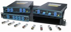
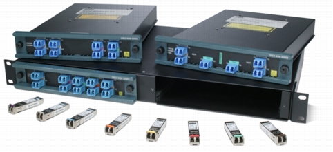
Figure 1. Cisco CWDM GBIC/SFP Solution
KEY FEATURES AND BENEFITS
Scalability
Easy Deployment and Flexible Implementation
High Availability
• Use of Layer 2 and Layer 3 redundancy and failover mechanisms at the channel endpoints (Cisco CWDM GBIC/SFP) to build highly available links
• Use of two-path link configurations in a ring architecture to provide protection from fiber cuts
Investment Protection
DEPLOYMENT SCENARIOS
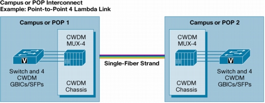
Point-to-Point Configuration
Figure 2. Point-to-Point Architecture (Dual-Fiber Link)
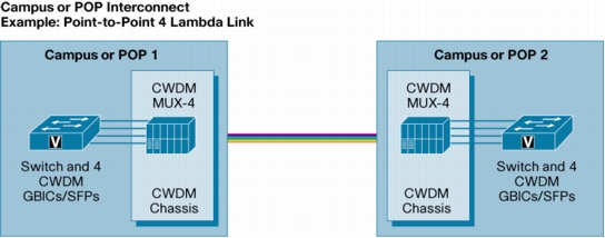
Figure 3. Point-to-Point Architecture (Single-Fiber Link)
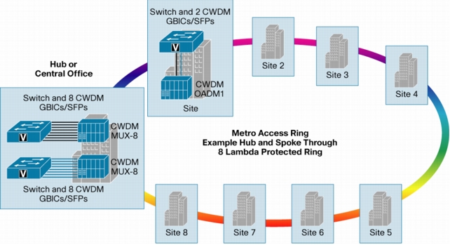
Hub-and-Spoke (Ring) Configuration
Figure 4. Hub-and-Spoke (Ring) Architecture
Mesh (Ring) Configuration
TECHNICAL SPECIFICATIONS
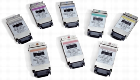
Cisco CWDM GBICs
Figure 5. Cisco CWDM GBICs
Performance
• 1.25 Gbps full-duplex links
• Optical link budget of 30 decibels (dB)
Platform Support
Connectors and Cabling
• Equipment: Standard GBIC interface
• Network: Dual SC/PC connector
Note: Only connections with patch cords with PC or UPC connectors are supported. Patch cords with APC connectors are not supported.
Environmental Conditions and Power Requirements
Table 1. Electrical Power Interface Data
|
Parameter |
Symbol |
Minimum |
Typical |
Maximum |
Units |
|
Supply Current
|
Is |
280 |
350 |
mA |
|
|
Maximum Voltage
|
Vmax |
6 |
V |
||
|
Surge Current
|
ISurge |
400 |
mA |
||
|
Input Voltage
|
Vcc |
4.75 |
5 |
5.25 |
V |
Optical Specifications
Table 2. Optical Parameters
|
Parameter |
Symbol |
Minimum |
Typical |
Maximum |
Units |
Notes and Conditions |
|
Transmitter Center Wavelength
|
wavelengthc |
(x-4) |
(x + 7) |
nm |
Available center wavelengths are 1470, 1490, 1510, 1530, 1550, 1570, 1590, and 1610 nm |
|
|
Side-Mode Suppression Ratio
|
SMSR |
30 |
dB |
|||
|
Transmitter Optical Output Power
|
Pout |
+1.0 |
+3.0 |
+5.0 |
dBm |
Average power coupled into single-mode fiber |
|
Receiver Optical Input Power (Bit error rate [BER] <10-12 with pseudo-random bit sequence [PRBS] 2-7-1)
|
Pin |
-29.0 |
-33.0 |
-7.0 |
dBm |
@ 1.25 Gbps, 140°F (60°C) case temperature |
|
Optical Input Wavelength
|
wavelengthin |
1450 |
1620 |
nm |
||
|
Transmitter Extinction Ratio
|
OMI |
9 |
dB |
|||
|
Dispersion Penalty at 100 km
|
3 |
dB |
@ 1.25 Gbps |
Note: Parameters are specified over temperature and at end of life unless otherwise noted.
Note: When shorter distances of single-mode fiber are used, it may be necessary to insert an inline optical attenuator in the link to avoid overloading the receiver:
Warranty
• Standard warranty: 90 days
• Extended warranty (option): Cisco CWDM GBICs can be covered through a Cisco SMARTnet® support contract for the Cisco switch or router chassis
Ordering Information
Table 3. Cisco CWDM GBIC Product Information
|
Product Number |
Description |
Color |
|
CWDM-GBIC-1470=
|
Cisco 1000BASE-CWDM GBIC, 1470 nm |
Gray |
|
CWDM-GBIC-1490=
|
Cisco 1000BASE-CWDM GBIC, 1490 nm |
Violet |
|
CWDM-GBIC-1510=
|
Cisco 1000BASE-CWDM GBIC, 1510 nm |
Blue |
|
CWDM-GBIC-1530=
|
Cisco 1000BASE-CWDM GBIC, 1530 nm |
Green |
|
CWDM-GBIC-1550=
|
Cisco 1000BASE-CWDM GBIC, 1550 nm |
Yellow |
|
CWDM-GBIC-1570=
|
Cisco 1000BASE-CWDM GBIC, 1570 nm |
Orange |
|
CWDM-GBIC-1590=
|
Cisco 1000BASE-CWDM GBIC, 1590 nm |
Red |
|
CWDM-GBIC-1610=
|
Cisco 1000BASE-CWDM GBIC, 1610 nm |
Brown |
|
CWDM-8GBIC-SET1=
|
Set of four pairs of Cisco 1000BASE-CWDM GBICs |
2 gray, blue, yellow, or red |
|
CWDM-8GBIC-SET2=
|
Set of four pairs of Cisco 1000BASE-CWDM GBICs |
2 violet, green, orange, or brown |
Regulatory and Standards Compliance
• Compatible with 1000BASE-X standard as specified in IEEE 802.3z
• Safety: Laser Class I 21CFR1040
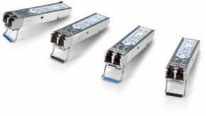
Cisco CWDM SFPs
Figure 6. Cisco CWDM SFPs
Performance
• Gigabit Ethernet 1.25 Gbps full-duplex links with an optical link budget of 29 dB
• Fibre Channel 1.06 and 2.12 Gbps full-duplex links with an optical link budget of 28 dB
Platform Support
Connectors and Cabling
• Equipment: Standard SFP interface
• Network: Dual LC/PC connector
Note: Only connections with patch cords with PC or UPC connectors are supported. Patch cords with APC connectors are not supported.
Environmental Conditions and Power Requirements
• Operating temperature range: 32 to 122°F (0 to 50°C)
• Storage temperature range: -40 to 185°F (-40 to 85°C)
Table 4. Electrical Power Interface Data
|
Parameter |
Symbol |
Minimum |
Typical |
Maximum |
Units |
|
Supply Current
|
Is |
220 |
300 |
mA |
|
|
Surge Current
|
ISurge |
+30 |
mA |
||
|
Input Voltage
|
Vmax |
3.1 |
3.3 |
3.5 |
V |
Table 5. Optical Parameters
|
Parameter |
Symbol |
Minimum |
Typical |
Maximum |
Units |
Notes and Conditions |
|
Transmitter Center Wavelength
|
wavelengthc |
(x-4) |
(x + 7) |
nm |
Available center wavelengths are 1470, 1490, 1510, 1530, 1550, 1570, 1590, and 1610 nm |
|
|
Side-Mode Suppression Ratio
|
SMSR |
30 |
dB |
|||
|
Transmitter Optical Output Power
|
Pout |
0 |
5.0 |
dBm |
Average power coupled into single-mode fiber |
|
|
Receiver Optical Input Power (BER <10-12 with PRBS 2-7-1)
|
Pin |
-28.0 |
-7.0 |
dBm |
@ 2.12 Gbps, 140°F (60°C) case temperature |
|
|
Receiver Optical Input Power (BER <10-12 with PRBS 2-7-1)
|
Pin |
-29.0 |
-7.0 |
dBm |
@ 1.25 Gbps, 140°F (60°C) case temperature |
|
|
Receiver Optical Input Wavelength
|
wavelengthin |
1450 |
1620 |
nm |
||
|
Transmitter Extinction Ratio
|
OMI |
9 |
dB |
|||
|
Dispersion Penalty at 100 km
|
3 |
dB |
@ 2.12 Gbps |
|||
|
Dispersion Penalty at 100 km
|
2 |
dB |
@ 1.25 Gbps |
Note: Parameters are specified over temperature and at end of life unless otherwise noted.
Note: When shorter distances of single-mode fiber are used, it may be necessary to insert an inline optical attenuator in the link to avoid overloading the receiver.
Warranty
• Standard warranty: 90 days
• Extended warranty (option): Available under a Cisco SMARTnet support contract for the Cisco switch or router chassis
Ordering Information
Table 6. Cisco CWDM SFP Product Information
|
Product Number |
Description |
Color |
|
CWDM-SFP-1470=
|
Cisco CWDM 1470-nm SFP; Gigabit Ethernet and 1 and 2 Gb Fibre Channel |
Gray |
|
CWDM-SFP-1490=
|
Cisco CWDM 1490-nm SFP; Gigabit Ethernet and 1 and 2 Gb Fibre Channel |
Violet |
|
CWDM-SFP-1510=
|
Cisco CWDM 1510-nm SFP; Gigabit Ethernet and 1 and 2 Gb Fibre Channel |
Blue |
|
CWDM-SFP-1530=
|
Cisco CWDM 1530-nm SFP; Gigabit Ethernet and 1 and 2-Gb Fibre Channel |
Green |
|
CWDM-SFP-1550=
|
Cisco CWDM 1550-nm SFP; Gigabit Ethernet and 1 and 2 Gb Fibre Channel |
Yellow |
|
CWDM-SFP-1570=
|
Cisco CWDM 1570-nm SFP; Gigabit Ethernet and 1 and 2 Gb Fibre Channel |
Orange |
|
CWDM-SFP-1590=
|
Cisco CWDM 1590-nm SFP; Gigabit Ethernet and 1 and 2 Gb Fibre Channel |
Red |
|
CWDM-SFP-1610=
|
Cisco CWDM 1610-nm SFP; Gigabit Ethernet and 1 and 2 Gb Fibre Channel |
Brown |
Regulatory and Standards Compliance
• Compliant with the ITU-T G.694.2 CWDM grid
• Compatible with 1000BASE-X standard as specified in IEEE 802.3z
• Compatible with Fibre Channel Draft Physical Interface Specification (FC-PI 10.0)
• Safety: Laser Class I 21CFR1040